Hydraulic accumulator
max. operating pressure 250 – 500 bar

Application
Hydraulic accumulators are used in hydraulic power workholding applications as energy storage for compensation of internal leakages or to compensate the volume in the case of temperature changes.
Energy storage
With intermittent cycles the rating of the pump and thereby energy can be saved. During the breaks the pump refills the hydraulic accumulator. If required, a higher flow rate is available for a short time.
Compensation for internal leakage
In power workholding most of the pressure generators work in a cycling mode controlled by a pressure switch. If hydraulic devices with internal leakages are connected, e.g. spool valves or rotary valve couplings, this leads to frequent switching on and off of the electrical drive motor. The use of a small hydraulic accumulator considerably reduces the number of switching cycles and saves the material as well as energy.
Volume compensation in case of temperature changes
If hydraulic clamping systems will be separated from the pressure generator, there are considerable changes of the clamping pressure in the case of temperature variations (reference value ±10 bar at ±1°C). A small hydraulic accumulator mounted at a protected place on the fixture, causes a volume compensation and reduces pressure variations. In addition a small leakage will not immediately result in a pressure drop. A pressure gauge for pressure control should be installed in any case.
Description
Liquids are more or less incompressible and therefore are not in the position to store pressure energy. For hydraulic accumulators the compressibility of nitrogen is used to store liquids. A gas-tight diaphragm separates the liquid zone from the gas zone.In the bottom of the diaphragm there is a valve disk that avoids a damage of the diaphragm if the hydraulic accumulator will be completely discharged.
Nitrogen is filled in at the screw plug and provided with the required preload. For this purpose an appropriate filling and testing fixture is required. The offered hydraulic accumulators correspond to the regulations of article 3 paragraph 3 of the directives for pressure devices 97/23/EG and are not allowed to bear the CE sign.
Legal requirements
For hydraulic accumulators the applicable regulations at the place of installation have to be considered before start up and during operation. The operator is exclusively responsible for the intended use and compliance of these regulations. In Germany the Classification as per German Health and Safety at Work Regulations (BetrSichV) is valid as legal basis. For the offered accumulator size the following is valid:
All works at the hydraulic or pneumatic ports of the hydraulic accumulator must only be effected by trained experts.
An expert is not required for the first acceptance.

| Item no. | CAD data | type | max. operating pressure [bar] | hydraulic port | outer Ø [mm] | |
|---|---|---|---|---|---|---|
|
Item no.
|
CAD data
|
Properties
| ||||
|
Item no.
|
CAD data
|
Properties
| ||||
|
Item no.
|
CAD data
|
Properties
| ||||
|
Item no.
|
CAD data
|
Properties
| ||||
|
Item no.
|
CAD data
|
Properties
| ||||
|
Item no.
|
CAD data
|
Properties
| ||||
|
Item no.
|
CAD data
|
Properties
| ||||
|
Item no.
|
CAD data
|
Properties
|
| Item no. | CAD data | Description |
|---|---|---|
|
Item no.
|
CAD data
|
Description
Pressure relief valve G1/2 - sealed
reaction pressure: 260 bar
as per data sheet F9.601
|
|
Item no.
|
CAD data
|
Description
Pressure relief valve G1/2 - sealed
reaction pressure: 315 bar
as per data sheet F9.601
|
|
Item no.
|
CAD data
|
Description
Pressure relief valve G1/2 - sealed
reaction pressure: 520 bar
as per data sheet F9.601
|
|
Item no.
|
CAD data
|
Description
Hexagon nut
M33 x 1.5 mm - 14 mm high
as per data sheet F9.601
|
|
Item no.
|
CAD data
|
Description
Double connector G1/4-G1/4
36 mm long
max. 500 bar, as per data sheet F9.300
|
|
Item no.
|
CAD data
|
Description
Thread reducing adaptor GWR 1/2 - 1/4
max. 315 bar, as per data sheet F9.300
|
|
Item no.
|
CAD data
|
Description
Pressure gauge union type A
with edge sealing ring
G1/4 - pipe Ø 8 mm
max. 500 bar, as per data sheet F9.300
|
|
Item no.
|
CAD data
|
Description
Tube male stud coupling D8S ED
G1/4 - pipe Ø 8 mm
max. 630 bar, as per data sheet F9.300
|
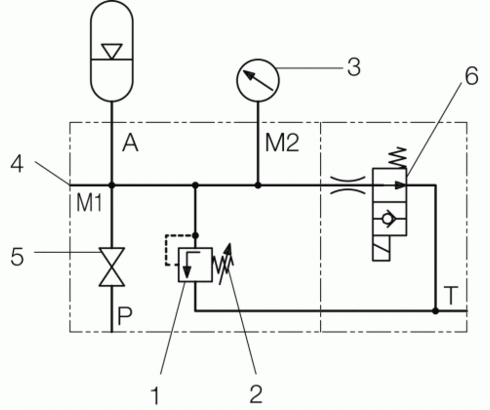
Hydraulic accumulators are subject to the valid national regulations and decrees at the installation location. In Germany, the "Technical Regulations for Pressure Reservoirs" (TRB) apply. These regulations demand the following equipment:
- Pressure relief valve (1)
- Relief device (2)
- Pressure gauge (3)
- Connection of a test pressure gauge (4)
- Shut-off valve optional (5)
- Electromagnetically-operated relief device (6)
1. Pressure relief valve
(Safety valve)
The pressure relief valve shall protect the hydraulic accumulator against a pressure increase by more than 10 % of the maximum operating pressure.Adjustment has to be effected with the maximum flow rate of the power unit. The reaction pressure of the pressure relief valve should be a little bit higher than the nominal pressure of the hydraulic accumulator.
The valve spindle of the pressure relief valve has to be secured against adjustment in the direction of higher pressure by means of distance plates and/or lead-sealing.
Important notes:
The pressure relief valve of the power unit must not be adjusted above the maximum operating pressure of the hydraulic accumulator. In the case of "small accumulators" with a nominal volume below 100 cm³ pressure safeguard can be realised by the pressure relief valve at the power unit, when the adjusting spindle is secured against exceeding the maximum operating pressure. If "small accumulators" are located on workpiece pallets, that will be uncoupled from the power unit, a pressure relief valve has to be provided on each pallet.
2. Relief device
Important note:
Before realising maintenance works at the hydraulic system or the fixture the hydraulic accumulator should be completely discharged. There are two possibilities:
To screw completely out the valve spindle of the pressure relief valve in the direction of low pressure or to open an installed shut-off valve (see example).
3. Pressure gauge
The pressure gauge shall indicate the actual pressure in the hydraulic accumulator. For this purpose a direct supply line has to be mounted. The pressure gauge at the power unit is not suitable for that purpose. The maximum operating pressure of the hydraulic accumulator shall be indicated by a marking on the pressure gauge scale. Alternatively also a labelled plate or tag can be fixed.
4. Connection of a test pressure gauge
For regular pressure tests a test pressure gauge can be connected.
5. Shut-off valve
By means of the shut-off valve the hydraulic accumulator can be separated from the power unit and the fixture in order to realise adjusting and maintenance works without danger.
Take advantage of the free benefits of our login area:
- CAD data download
- Download operating instructions
Welcome back! Log in to your already existing user account.