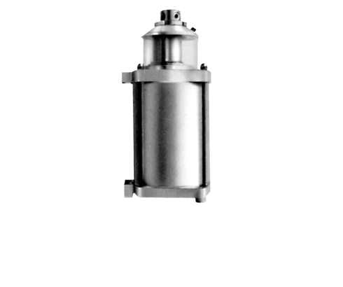
Intensifiers air – oil, 57 - 188 cm3
max. operating pressure up to 500 bar
single acting, with oil reservoir

Description
This pneumatic-hydraulic intensifier can be used as a pressure generator where live cables are not possible or suitable, e.g. in hazardous surroundings. Only single-acting cylinders can be connected. The cylinder volume should utilise the stroke volume of the intensifier only up to 60 - 70% so as to have some reserve left.
When designing fixtures, some features of the air intensifier should be taken into account:
1. Extend cylinder
Intensifiers are liable to release the effective oil volume very quickly within 1 second. The oil speed depends only on the flow rate of the compressed air. This may cause malfunctions in clamping elements where the maximum flow rate is limited (swing clamps, work supports). In those cases a flow control valve must be provided on the oil side.
2. Pressure build-up
After extending the cylinders, pressure build-up is relatively slow, according to the nominal bore of the pneumatic piping and air pressure. At 6 bar the sextuple working volume must be fed, which takes approx. 3 seconds.
3. Unclamping
For this purpose, the air volume accumulated must first be reduced to a residual pressure below 0.2 bar, before the connected hydraulic cylinders retract. The high-speed vent valve available as an accessory allows for a pressure release time of approx. 2 seconds at an initial pressure of 6 bar.
4. Pressure adjustment
The hydraulic operating pressure can only be adjusted by means of a pressure reducing valve at the pneumatic side.
We recommend our service unit part no. 9511 005.
Important note: The maximum operating pressure on the hydraulic side is determined by the component having the smallest admissible operating pressure. The pneumatic adjustment must be checked by a pressure gauge located on the hydraulic side.
5. Replenishment
Any minor leak losses are compensated after unclamping by replenishing out of the oil tank. This requires a well vented system and an oil filler screw slightly opened.
| Item no. | CAD data | type | type | functioning | hydraulic port | |
|---|---|---|---|---|---|---|
|
Item no.
|
Properties
| |||||
|
Item no.
|
Properties
| |||||
|
Item no.
|
Properties
| |||||
|
Item no.
|
Properties
|
| Item no. | CAD data | Description |
|---|---|---|
|
Item no.
|
Description
Foot valve with catch
including cover
as per data sheet D8.600
|
|
|
Item no.
|
CAD data
|
Description
Thread reducing adaptor GWR 3/8ED - 1/4
max. 400 bar, as per data sheet F9.300
|
|
Item no.
|
Description
Hand lever valve with catch
as per data sheet D8.600
|
|
|
Item no.
|
Description
High-speed vent valve G 3/8
as per data sheet D8.770
|
|
|
Item no.
|
Description
Check valve - size 1/4
as per data sheet D8.770
|
|
|
Item no.
|
Description
Silencer - size 1/8
as per data sheet D8.600
|
|
|
Item no.
|
Description
Socket end - size 1/8
as per data sheet D8.770
|
|
|
Item no.
|
CAD data
|
Description
Pressure gauge union type A
with edge sealing ring
G1/4 - pipe Ø 8 mm
max. 500 bar, as per data sheet F9.300
|
|
Item no.
|
CAD data
|
Description
Tube male stud coupling D8L ED
G1/4 - pipe Ø 8 mm
max. 250 bar, as per data sheet F9.300
|
|
Item no.
|
Description
Tube male stud coupling D12L
as per data sheet D8.770
|
Take advantage of the free benefits of our login area:
- CAD data download
- Download operating instructions
Welcome back! Log in to your already existing user account.