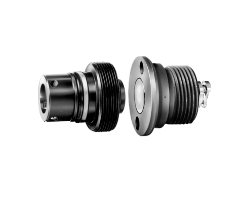
Threaded coupling elements
Application
Compared to other coupling elements the threaded coupling elements are very compact devices.
lf the slide movement of the workpiece carrier is to be used or if a fixture is to be connected to the base plate without lines, the threaded nipple and the coupling mechanisms can be directly screwed into the parts which are to be connected. The coupling mechanisms have the advantage that they are flush-faced in uncoupled mode.
Flange-type housings are available to simplify the manufacture of the fixture mounting hole contours. In cramped conditions it is possible to make and install the flange-type housing retrospectively.
The fixture bodies which are to take up the coupling parts have to be guided 2 – 3 mm in a parallel motion before they are coupled.
The axial forces which arise during the pres sure build-up in coupled mode have to be absorbed outside the coupling parts.
The long coupling nipple provided with a preloaded valve (PV) can be installed in the return or unclamping line of a clamping fixture.
The valve limits a possible pressure build up in uncoupled (static) condition to approx. 5 bar. The preloaded valve is not effective in coupled condition.
Depending on the version the coupling elements can either be coupled in energized or in deenergized mode only. The perating mode depends on the type of sealing elements which are used and can be taken from the table above.
The max. positioning tolerances in axial and radial direction are indicated in the above table. To transmit compressed air and vacuum use only the coupling elements for “depressurised coupling”.
The sealing areas at the side of the coupling elements have to be cleaned before coupling, to ensure the connection in coupled mode. We recommend to wash the elements and finally clean them with compressed air. Protection covers should be used as far as possible.
Previous cleaning of the even sealing areas is possible by means of rubber wipers.
| Item no. | CAD data | type | type | max. operating pressure [bar] | component | |
|---|---|---|---|---|---|---|
|
Item no.
|
CAD data
|
Properties
|
| Item no. | CAD data | Description |
|---|---|---|
|
Item no.
|
Description
Seal kit for 0460-654
as per data sheet S0.001
|
|
|
Item no.
|
Description
Seal kit for 0460-655
as per data sheet S0.001
|
|
|
Item no.
|
CAD data
|
Description
Flange-type housing ND5
max. 500 bar, as per data sheet F9.430
|
|
Item no.
|
CAD data
|
Description
Flange-type housing ND3
max. 500 bar, as per data sheet F9.430
|
|
Item no.
|
Description
Screw tool ND3
for coupling mechanism and nipple
as per data sheet F9.430
|
|
|
Item no.
|
Description
Screw tool ND5
for coupling mechanism and nipple
as per data sheet F9.428
|
Take advantage of the free benefits of our login area:
- CAD data download
- Download operating instructions
Welcome back! Log in to your already existing user account.
