Hollow cylinders
single and double acting
max. operating pressure 500 bar
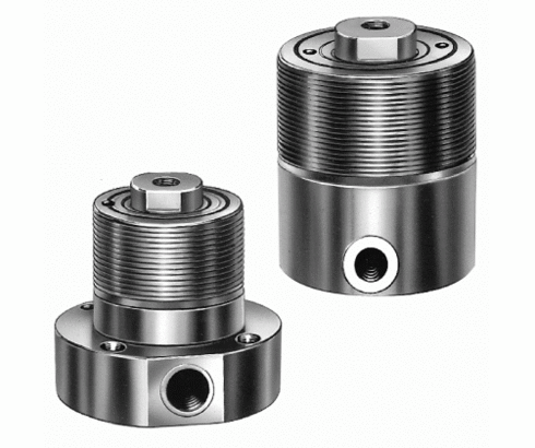
Hollow-piston cylinders are especially suitable for clamping workpieces that have a through hole or opening.
The piston has a through hole with an internal thread.
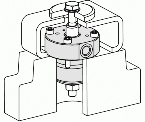
In connection with a standard tie rod and C-washer combination a variety of applications is possible (see application examples).
After the workpiece has been inserted and centred by hand, the C-washer can be pushed onto the tie rod and then clamped hydraulically.
Compared to mechanical clamping with clamping screws this has significant advantages:
- The clamping force can be hydraulically adjusted with precision and high repetitive accuracy
- The operator can fully concentrate on the correct position of the workpiece
- A significant time saving
| Item no. | CAD data | stroke [mm] | functioning | piston diameter [mm] | max. force to push [kN] | |
|---|---|---|---|---|---|---|
|
Item no.
|
CAD data
|
Properties
| ||||
|
Item no.
|
CAD data
|
Properties
|
| Item no. | CAD data | Description |
|---|---|---|
|
Item no.
|
Description
|
|
|
Item no.
|
CAD data
|
Description
Lock nut DIN 1804
M120 x 2 mm
as per data sheet B1.7441
|
|
Item no.
|
Description
|
|
|
Item no.
|
CAD data
|
Description
Flange nut DIN 1804
M48 x 1,5 mm
see page B1.309
|
|
Item no.
|
CAD data
|
Description
Flange nut
M60 x 1,5 mm W
black oxided
see page B1.460
|
|
Item no.
|
CAD data
|
Description
Flange nut DIN 1804
M90 x 2 mm
see page B1.309
|
|
Item no.
|
CAD data
|
Description
Flange nut DIN 1804
M75 x 1,5 mm
see page B1.309
|
|
Item no.
|
CAD data
|
Description
Flange nut DIN 1804
M40 x 1,5 mm
see page B1.309
|
|
Item no.
|
CAD data
|
Description
Socket head cap screw
M8 x 20 mm, 8.8, galvanized
as per data sheet B1.7441
|
|
Item no.
|
CAD data
|
Description
Flange for hollow-piston cylinder 1756-XXX
Ø 105 x 20 mm
as per data sheet B1.7441
|
Hollow-piston cylinders in combination with push-pull bolt and “C”-washer can be used advantageously in many cases to clamp workpieces with centre openings.
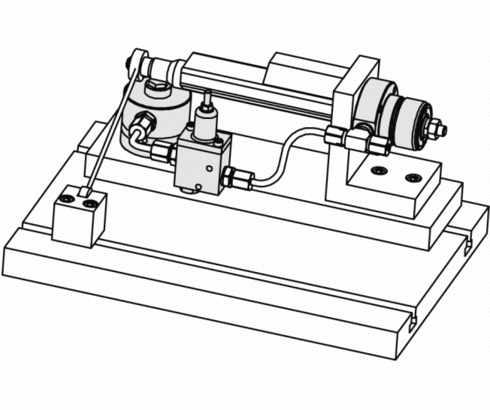
On the shown machine table, the workpiece is clamped with a hollow-piston cylinder and additionally supported with a work support, controlled by a sequence valve.
The support plunger of the work support is retracted in off-position to facilitate workpiece loading. Contact is effected by means of spring force. The savings in workpiece exchange time, compared to a mechanical clamping system amounts to 58%.
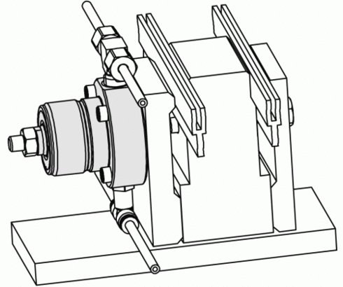
This clamping fixture is for milling operation on a light extruded rail. Workholding by means of hollow-piston cylinders in individual clamping stations mounted on a base plate. Positioning and support of the rail is effected with two longitudinal members matching the cross section of the rail.
Take advantage of the free benefits of our login area:
- CAD data download
- Download operating instructions
Welcome back! Log in to your already existing user account.


