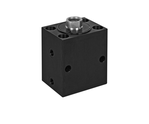
Block Cylinders S
use as punching cylinder max. 250 bar
Hydraulic block cylinders are universally used for all linear movements with high force requirements and very small dimensions. The block cylinder S can withstand high mechanical and thermal loads.
Its preferred applications are:
- Punching (Max. operating pressure 250 bar *)
- Deburring
- Forming such as bending, riveting, stamping
- In mould making for actuating core pullers and slides
- In automatic manufacturing systems with very short cycle times
The double-acting function ensures high function safety as well as exactly calculable and repeatable stroke times.
The block cylinders S are equipped with the latest sealing technology, so that optimally adapted versions are available depending on the operating pressure (250 or 500 bar), temperature and hydraulic fluid. At the piston rod outlet, the dirt wipers are largely protected against swarf by the recessed installation.
All series are equipped with piston and rod guide rings which absorb side loads between the sliding components and prevent direct metal contact.
This increases the service life and minimizes leakage. The admissible piston side load depends on the stroke and can be taken from the diagrams on page 5 of the catalogue sheet. The internal piston stops are of sturdy design. The admissible piston speed depends on the mass fixed to the piston and can be read in the diagram on page 5 of the catalogue sheet.
*) Maximum operating pressure 250 bar Required for punching applications due to the high load caused by the cutting impact. Even with the high-pressure version (500 bar), the pressure must be limited to 250 bar. The advantage of this is the longer service life of the high-pressure seals.
| Item no. | CAD data | type | stroke [mm] | functioning | stroke end cushioning | |
|---|---|---|---|---|---|---|
|
Item no.
|
CAD data
|
Properties
| ||||
|
Item no.
|
CAD data
|
Properties
| ||||
|
Item no.
|
CAD data
|
Properties
| ||||
|
Item no.
|
CAD data
|
Properties
| ||||
|
Item no.
|
CAD data
|
Properties
| ||||
|
Item no.
|
CAD data
|
Properties
| ||||
|
Item no.
|
CAD data
|
Properties
| ||||
|
Item no.
|
CAD data
|
Properties
| ||||
|
Item no.
|
CAD data
|
Properties
| ||||
|
Item no.
|
CAD data
|
Properties
|
| Item no. | CAD data | Description |
|---|---|---|
|
Item no.
|
Description
O-ring 8 x 1.5 mm, FKM
as per data sheet B1.5091
|
|
|
Item no.
|
Description
O-ring 5 x 1.5 mm
as per data sheet C2.320
|
|
|
Item no.
|
CAD data
|
Description
O-ring 7 x 1.5 mm, NBR
as per data sheet B1.5091
|
|
Item no.
|
CAD data
|
Description
O-ring 8 x 1.5 mm, NBR
as per data sheet B1.5091
|
|
Item no.
|
CAD data
|
Description
O-ring 10 x 2 mm, NBR
as per data sheet B1.5091
|
|
Item no.
|
CAD data
|
Description
O-ring 7 x 1.5 mm, FKM
as per data sheet B1.5091
|
|
Item no.
|
CAD data
|
Description
O-ring 10 x 2 mm, FKM
as per data sheet B1.5091
|
|
Item no.
|
Description
O-ring 5 x 1.5 mm - FKM
as per data sheet F9.732
|
Take advantage of the free benefits of our login area:
- CAD data download
- Download operating instructions
Welcome back! Log in to your already existing user account.
