Pneumatic swing clamp
double acting, max. operating pressure 7 bar
Application
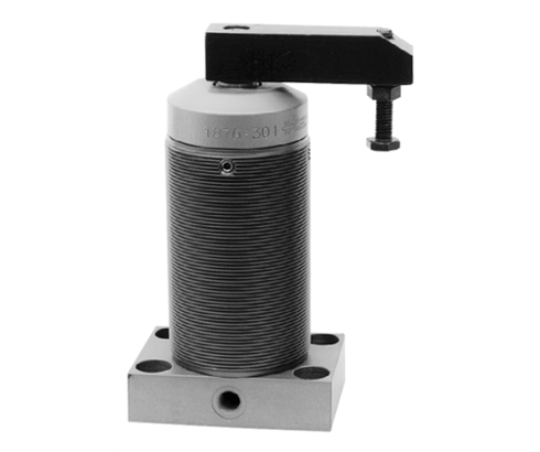
Pneumatic swing clamps are used for clamping of workpieces when it is essential to keep the clamping area free of straps and clamping components for unrestricted workpiece loading and unloading. Pneumatic swing clamps are used for applications which require only low clamping forces. The installed magnetic piston allows monitoring of clamping and unclamping position.
Function
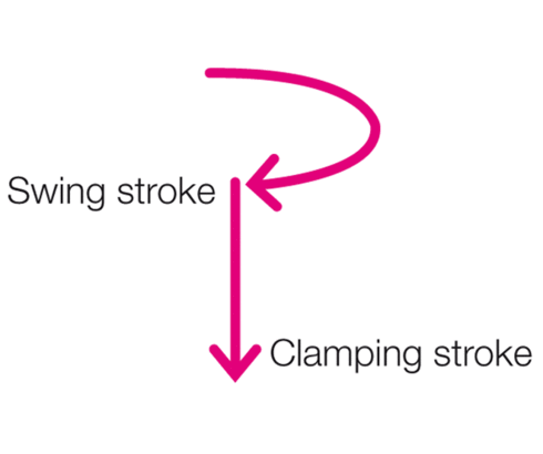
A swing clamp is a pull-type cylinder where a part of the total stroke is used to swing the piston (swing stroke) and the screwed-on clamping arm.
Description
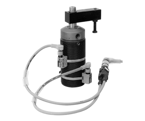
When pressurising the element, the clamping arm swings and lowers by 90° to the clamping position and then lowers to the clamping point. The position monitoring gives the required information regarding the position of the piston, but not regarding the position of the clamping arm. Monitoring is made by electronic sensors (see accessory) which detect the magnetic field of the magnetic piston. The switching points can be continuously adjusted by displacement of the magnetic sensors.
Material
The swing clamps are supplied in corrosion resistant quality. Guide bushing, housing, piston, and flange are made of anodized aluminium. The piston rod is made of stainless steel.
Swing direction
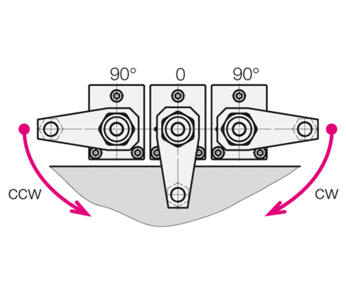
90° swing angle, alternatively available with clockwise or counterclockwise swing motion. "Swing direction cw" designates the clockwise rotation of the piston starting from the extended position (off-position). Accordingly, the "swing direction ccw" is a counterclockwise rotation.
On fixtures flange-type swing clamps (flange is an accessory) or threaded-body types with corresponding collar nuts can be easily adjusted to different workpiece heights.
A permanent magnet is fixed to the piston, and its magnetic field is detected by a magnetic electronic sensor.
Compared with traditional reed switches the electronic magnetic sensors offer the following advantages:
- indifference to shock and vibration
- bounce-free output signal
- only one switching point
- wear resistant
- protection against reverse battery
- protected against short circuits
Electrical connection is made as per traditional inductive proximity switches. Up to four magnetic sensors can be connected in series.
Fixing of the magnetic sensors at the threaded-body type J7.201 is made by means of a hose clamp at the body of the swing clamp. At the block type J7.202 and at the top flange type J7.203 they are fixed in the slots of the body.
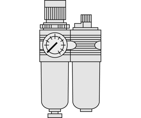
Operating of these pneumatic elements has to be effected with an additional service unit in order to guarantee that the clamping elements are supplied with correctly prepared compressed air.
In any case the swing motion must not be impeded.
When using special clamping arms with other lengths, the corresponding operating pressures as shown in the clamping force diagram must not be exceeded.
| Item no. | CAD data | functioning | piston diameter [mm] | rod diameter [mm] | max. operating pressure [bar] | |
|---|---|---|---|---|---|---|
|
Item no.
|
CAD data
|
Properties
| ||||
|
Item no.
|
CAD data
|
Properties
| ||||
|
Item no.
|
CAD data
|
Properties
| ||||
|
Item no.
|
CAD data
|
Properties
| ||||
|
Item no.
|
CAD data
|
Properties
| ||||
|
Item no.
|
CAD data
|
Properties
| ||||
|
Item no.
|
CAD data
|
Properties
| ||||
|
Item no.
|
CAD data
|
Properties
| ||||
|
Item no.
|
CAD data
|
Properties
| ||||
|
Item no.
|
CAD data
|
Properties
|
| Item no. | CAD data | Description |
|---|---|---|
|
Item no.
|
CAD data
|
Description
Clamping arm 30 mm
for 1873-X05
as per data sheet J7.201
|
|
Item no.
|
CAD data
|
Description
Clamping arm 35 mm
for 1874-X03
as per data sheet J7.201
|
|
Item no.
|
CAD data
|
Description
Clamping arm 50 mm
for 1875-X03
as per data sheet J7.201
|
|
Item no.
|
CAD data
|
Description
Clamping arm 60 mm
for 1876-X03
as per data sheet J7.201
|
|
Item no.
|
CAD data
|
Description
Clamping arm 75 mm
for 1877-X03
as per data sheet J7.201
|
|
Item no.
|
CAD data
|
Description
Flange for 1X73-XXX
as per data sheet J7.201
|
|
Item no.
|
CAD data
|
Description
Flange for 1X74-XXX
as per data sheet J7.201
|
|
Item no.
|
CAD data
|
Description
Flange for 1X75-XXX
as per data sheet J7.201
|
|
Item no.
|
CAD data
|
Description
Flange for 1X76-XXX
as per data sheet J7.201
|
|
Item no.
|
CAD data
|
Description
Flange for 1X77-XXX
as per data sheet J7.201
|
Clamping arm location
To locate clamping arms or clamps, normally a cone seat at the piston of the swing clamp is used. The cone ratio is 1 to 10. This location is the same for all types of one size.
Operating pressure
The maximum admissible operating pressure is 7 bar. The minimum admissible operating pressure is 3 bar.
Tolerance of the swing angle
is ±2°.
Dimension tolerances
Dimensions without tolerance data correspond to the general tolerances in accordance with DIN ISO 2768 -mH.
Swing clamps with magnetic sensors
A permanent magnet is fixed to the piston, and its magnetic field is detected by a magnetic electronic sensor.
- Influencing the magnetic field by adjacent, magnetisable components (e.g. steel parts):
In order to guarantee perfect functioning, it is recommended to maintain a distance of at least 25 to 30 mm between magnetic sensor and magnetisable components. The function is indeed possible with a smaller distance but this depends highly on the individual circumstances for fitting. Thus ordinary steel bolts can also normally be used for fastening the cylinder. In borderline cases, screws of non-magnetisable steel (e.g. VA screws) can cause an improvement in the magnetic field.
Influencing the magnetic field by adjacent magnetic sensors
If several block cylinders with magnetic sensors are installed directly adjacent to one another, the magnetic sensors can have a reciprocal influence and malfunctions occur. A magnetisable steel sheet can help, placed between the block cylinders, i.e. magnetic sensors, as a shield.
- Demands on voltage supply
see data sheet G2.140
- Path and switching hysteresis of approx. 3 mm
This has to be considered already when adjusting the magnetic sensors. For static pistons, the magnetic sensor must always be pushed forward to the piston from the opposite direction.
Take advantage of the free benefits of our login area:
- CAD data download
- Download operating instructions
Welcome back! Log in to your already existing user account.
