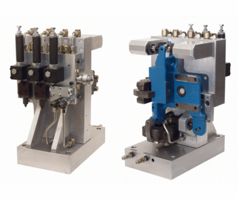
Valve module combinations

The valve module combination is a valve unit composed of individual modules. It is used to control complex hydraulic clamping fixtures. In order to fix safely workpieces in clamping fixtures, functions as positioning, clamping and supporting have to be effected in a determined sequence. In some applications it is required to realise the individual functions with reduced clamping pressures in order to guarantee optimum workpiece clamping.
For this purpose sequence valves and pressure reducing valves are integrated in the hydraulic clamping circuit. Therefore considerably longer lines are required for tubing as well as for drilled channels. Due to the use of valve module combination the required line length is considerably reduced, since all required control and pressure valves are directly arranged at the unit.
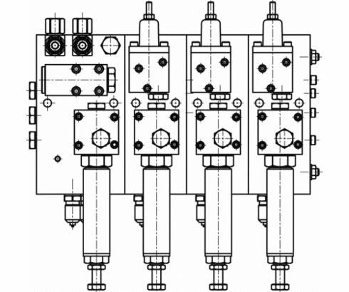
The valve module combination consists of an input module and up to three series modules (for linkage of further modules please consult us).
In the input module the following hydraulic function elements are integrated:
- Flow control valve with connected line filter for both inputs to reduce the flow rate and to filter the fluid
- Pilot-operated check valve to protect the clamping circuit in the case of pressure drop e.g. due to line break.
- Pressure reducing valve to reduce the pressure for the first control function at the fixture.
- Two mini measuring connections to connect a pressure gauge for pressure adjustment.
The series modules are directly linked to the input module. Thereby further clamping functions can be realised.
- The modules are equipped with the following hydraulic function elements:
- Sequence valve to realise one or several switching sequences (connected in series in the linked arrangement)
- Pressure reducing valve to reduce the pressure in the corresponding switching sequence.
- Mini measuring connection to connect a pressure gauge for pressure adjustment.
- In the base plates of the modules additional channels are provided which can be used as hydraulic / pneumatic channels or for the routing of electric lines. If permanent visual pressure monitoring is required, pressure gauges can be retrofitted.
| Item no. | CAD data | Description |
|---|---|---|
|
Item no.
|
CAD data
|
Description
Pressure gauge union type B
with edge sealing ring
G1/4 - pipe Ø 8 mm
max. 500 bar, as per data sheet F9.300
|
|
Item no.
|
CAD data
|
Description
Tube male stud coupling D8S
G1/4 - pipe Ø 8 mm
max. 400 bar, as per data sheet F9.300
|
|
Item no.
|
CAD data
|
Description
Pressure gauge 0 – 400 bar
with glycerine filling
with sealing plug
ports G1/4
as per data sheet F9.300
|
|
Item no.
|
CAD data
|
Description
Pressure gauge 0 – 400 bar
with glycerine filling
with screw plug SW 9
ports G1/4
as per data sheet F9.300
|
The figures show a hydraulic clamping fixture for machining of a power unit carrier for an agricultural tractor. The workpiece will be machined from four sides in a horizontal machining centre. Machining of the back of the workpiece is made from the back through the basic body.
Slide pivot clamps, universal cylinders, one work support and for ”floating clamping” of the two upper straps threaded-body cylinders with locking pistons are used as clamping elements. The hydraulic elements are controlled by the valve module combination mounted at the back.
Sequence of the clamping cycle
Step 1:
Clamping with the first slide pivot clamp against fixed datums, as well as
lateral positioning by means of an universal cylinder.
Step 2:
First sequence valve opens, work support moves against the lower side of the workpiece and is hydraulically locked.
Step 3:
Second sequence valve opens, two each oppositely arranged threaded-body cylinders with locking piston clamp both upper straps of the workpiece by ”floating clamping”. At the same time, the second slide pivot clamp clamps onto the work support.
Take advantage of the free benefits of our login area:
- CAD data download
- Download operating instructions
Welcome back! Log in to your already existing user account.